Assignment Description
I was assigned to design a non-ratcheting, 3/8 inch drive instrumented torque wrench
rated for 600 in-lbf.
The torque will be transduced by strain gauges on the sides of the torque wrench.
The design goal is to maximize the voltage output of the wrench (mV/V) at the rated torque.
The design is required to attain at least 1.0 mV/V output at the rated torque of
600 in-lbf. Higher output will lead to more sensitivity and improved signal-to-noise ratio.
The constraints are that the wrench must not fail due to static loading, crack growth, or fatigue.
The wrench must sustain a fully reversed torque of
T = ±600 in-lbf for
106 cycles.
Design will include selecting an appropriate material and dimensions to meet or exceed the
following requirements:
- At least 1.0 mV/V output at 600 in-lbf
- Safety factor Xo = 4 for yield or brittle failure
- Safety factor XK = 2 for crack growth from a 0.04 in crack
- Fatigue safety factor XS = 1.5
- Material must be steel, aluminum, or titanium alloy
Basic Design and Hand Calculations
Material Selection
The wrench will be one solid body to avoid bonding weaknesses. Therefore, a single
material was selected for the core structure.
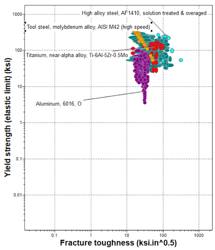
The material must not be brittle, as a large elastic regime improves strain-gauge sensitivity.
High fracture toughness is also critical due to reduced cross-section at the gauge location.
Aluminum alloys have far lower strength and toughness than steel and titanium.
While M-series tooling steels have high stiffness, they generally exhibit reduced
fracture toughness.
High Alloy Steel AF1410 was selected due to its high yield strength,
fracture toughness, and Young’s modulus.
High Alloy Steel AF1410
- Young’s Modulus: 29.4 × 10⁶ psi
- Poisson’s Ratio: 0.3
- Yield Strength: 215 ksi
- Fatigue Strength: 94.3 ksi
- Fracture Toughness: 137 ksi√in
The wrench was designed for a maximum torque of 1200 in-lbf (100 ft-lbf).
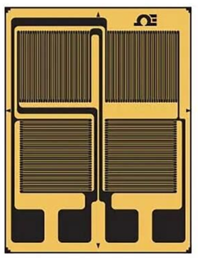
A full Wheatstone bridge strain gauge configuration was selected, providing twice
the sensitivity of a half-bridge.
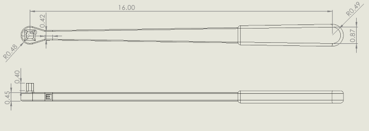
Basic Dimensions
- L = 16 in
- h = 0.65 in
- b = 0.45 in
- c = 1.0 in
Analytical Results
- Maximum Normal Stress: 37.87 ksi
- Deflection: 0.338 in
- Strength Safety Factor: 18.93
- Crack Growth Safety Factor: 18.22
- Fatigue Safety Factor: 4.98
- Strain at Gauge: 603.8 µε
- Output at 600 in-lbf: 1.2076 mV/V
CAD Model
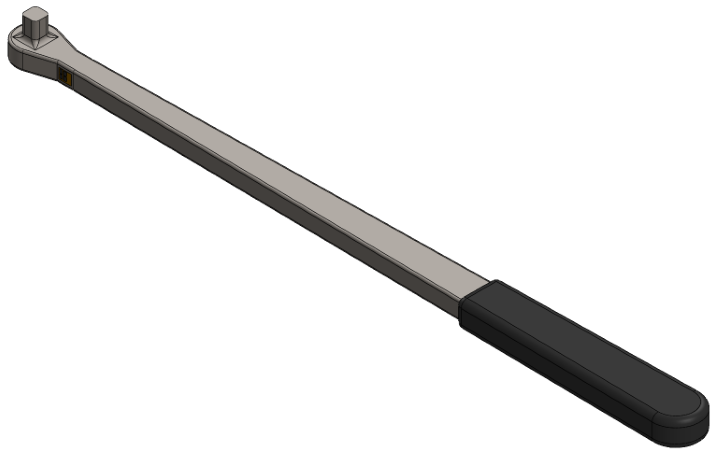
The CAD model follows the analytical dimensions. The handle width is reduced
to 85% at the strain gauge section, with fillets applied to reduce stress concentrations.
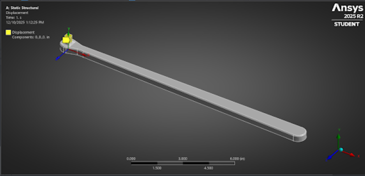
FEM Analysis
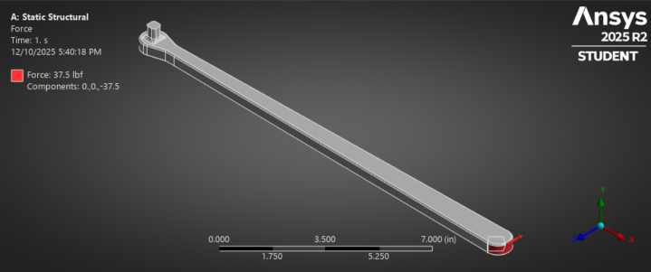
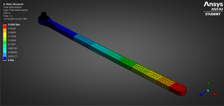
Boundary Conditions
Zero displacement was applied at the drive, with a 37.5 lbf load applied at the grip,
corresponding to 600 in-lbf torque.
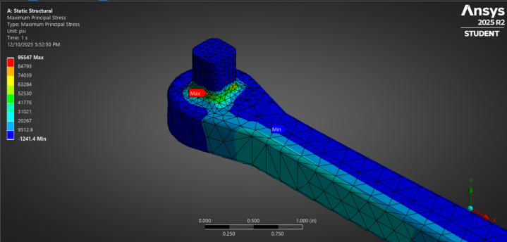
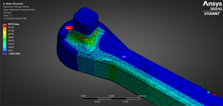
FEM Solution
The reduced thickness at the strain gauge increased local strain by ~66%.
Peak strain reached 1016 µε.
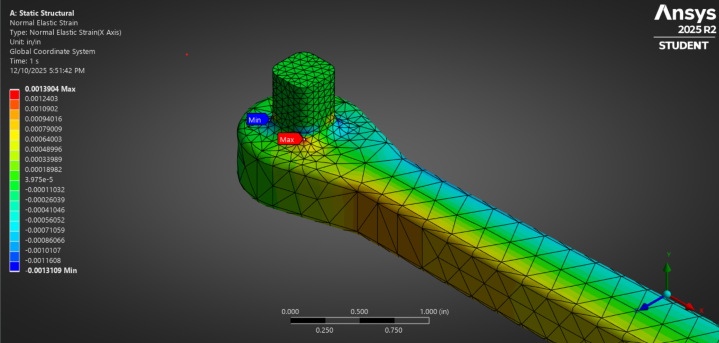
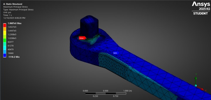
Stress concentrations at the drive reached 95.5 ksi, exceeding analytical predictions.
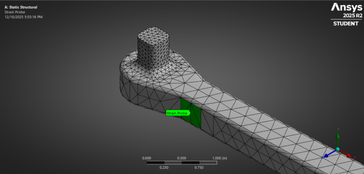
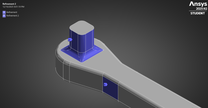
Post-Refinement Results
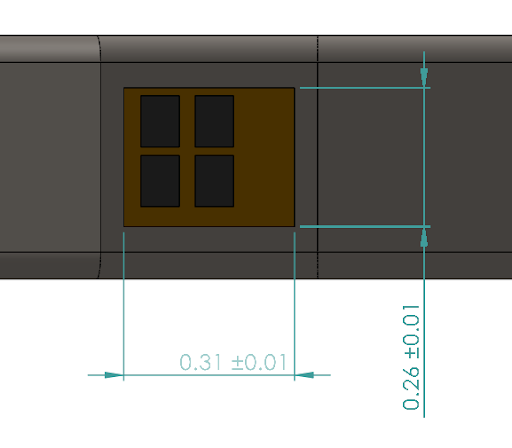
Strain Gauge
- Type: SgT-2/1000-FB41
- Configuration: Full Wheatstone Bridge
- Manufacturer: Omega
- Supplier: DigiKey
- Carrier Size: 0.315 × 0.256 in
- Grid Size: 0.071 × 0.094 in
- VRMS: 12
- Temperature Compensation: Steel