Project - Airbrakes.
Airbrake Design and Analysis
Interactive Model
During the 2025–2026 IREC design season I worked on the Airbrakes system for our team.
Flight scoring is based on the demonstrated altitude achieved relative to target apogee and successful recovery. The accuracy of the launch vehicle's actual apogee is worth 70% of the point value of flight performance, and so trajectory planning is important. One strategy in reducing the error between target apogee and flown apogee is the implementation of an Airbrake system.
In order to evaluate different designs for our trade study, we need to characterize the environment we expect deploy the Airbrakes. The important conditions to consider are the wind speed, altitude, and air density. Using this information along with a dynamic model of our rocket we can start approximating the vehicle dynamics during the coasting phase. Finally we need to determine a maximum change in altitude as a system parameter. With Airbrakes the best approach is to design a rocket that overshoots the target apogee. The altitude change required by our system can be approximated by taking the overshoot value, adding uncertainty and multiplying by a factor of safety. Then the model can be used to predict how Airbrakes of different cross sectional area and drag coefficients operate. For preliminary analysis we will not take into account active control, but rather model Airbrakes as a system that transitions from the neutral state to an active state where it is fully deployed and does not actuate further during flight.
- Pressure is approximated using the barometric formula for linearly decreasing temperature
- Density is derived by treating air as an ideal gas with specific gas constant ~287 J/kgK
Air Density as a function of altitude
I created a basic 1-D dynamic model in MATLAB to simulate the behavior of the Airbrakes system. The model accounts for the forces acting on the rocket during the coasting phase, including gravity, and aerodynamic drag. The Airbrakes are modeled as a system that can be deployed to increase drag and reduce altitude overshoot. The drag force is split into the nominal drag of the launch vehicle \(F_{d,LV}\) and the additional drag from the Airbrakes \(F_{d,brake}\).
Equation of Motion for Airbrakes System
Using the above formulation the following system performance were produced for an airbrake system with a \(C_d=1.3\) and \(A_{brake}=0.202 ft^2\)
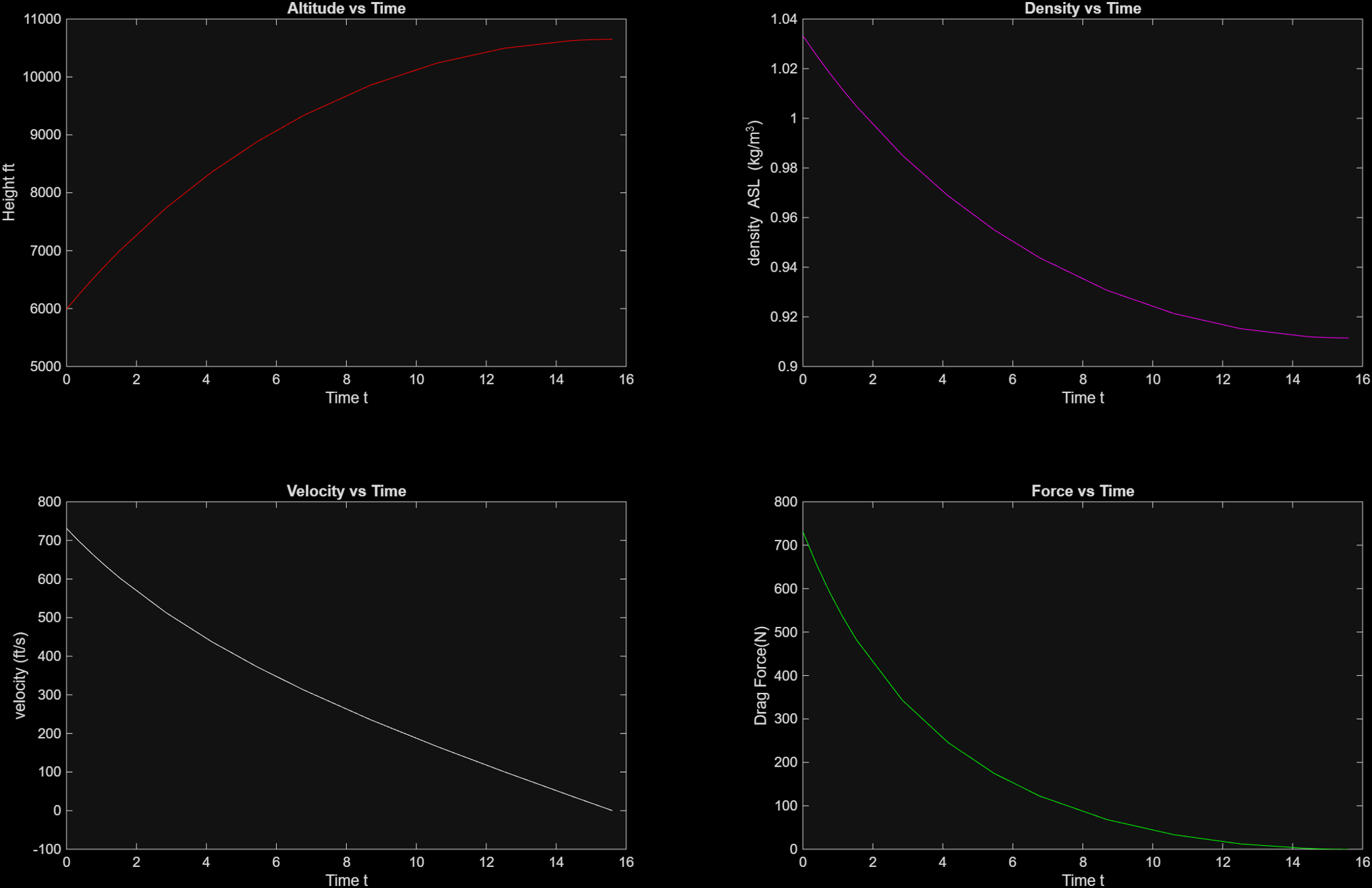
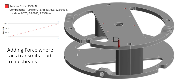
The maximum loading from the analysis is around \(720 N\) which is well within the structural limits of my integration structure design. The system is able to reduce the altitude overshoot by around 1000 ft which is a significant improvement in performance. Future work on this project will include the implementation of an active control system for the Airbrakes and further optimization of the design parameters.
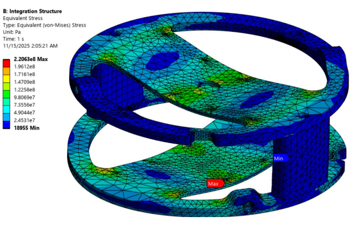
Design decisions were documented on Confluence from conception to final design. The design process included a trade study of different Airbrakes configurations, analysis of the system's performance using the dynamic model, and testing of the system's structural integrity using finite element analysis (FEA). The final design was selected based on its ability to meet the performance requirements while also being feasible to manufacture and integrate into the launch vehicle.